Accelerometer connection
September 26th, 2010
I am currently connecting the memsic 2125 dual axis accelerometer to an old floppy ribbon cable.
The cable will also carry current to a LED flashlight that will illuminate the path of the robot as well as an Infrared LED that will command neighboring devices that have IR remote control ![]() ( Tv , aircondition , etc. )
( Tv , aircondition , etc. )
I ve found code to integrate it with arduino http://arduino.cc/en/Tutorial/Memsic2125?from=Tutorial.AccelerometerMemsic2125
Code:
/* | |
Memsic2125 | |
| |
Read the Memsic 2125 two-axis accelerometer. Converts the | |
pulses output by the 2125 into milli-g's (1/1000 of earth's | |
gravity) and prints them over the serial connection to the | |
computer. | |
| |
The circuit: | |
* X output of accelerometer to digital pin 2 | |
* Y output of accelerometer to digital pin 3 | |
* +V of accelerometer to +5V | |
* GND of accelerometer to ground | |
| |
http://www.arduino.cc/en/Tutorial/Memsic2125 | |
| |
created 6 Nov 2008 | |
by David A. Mellis | |
modified 30 Jun 2009 | |
by Tom Igoe | |
| |
This example code is in the public domain. | |
| |
*/ | |
| |
// these constants won't change: | |
const int xPin = 2; // X output of the accelerometer | |
const int yPin = 3; // Y output of the accelerometer | |
| |
void setup() { | |
// initialize serial communications: | |
Serial.begin(9600); | |
// initialize the pins connected to the accelerometer | |
// as inputs: | |
pinMode(xPin, INPUT); | |
pinMode(yPin, INPUT); | |
} | |
| |
void loop() { | |
// variables to read the pulse widths: | |
int pulseX, pulseY; | |
// variables to contain the resulting accelerations | |
int accelerationX, accelerationY; | |
| |
// read pulse from x- and y-axes: | |
pulseX = pulseIn(xPin,HIGH); | |
pulseY = pulseIn(yPin,HIGH); | |
| |
// convert the pulse width into acceleration | |
// accelerationX and accelerationY are in milli-g's: | |
// earth's gravity is 1000 milli-g's, or 1g. | |
accelerationX = ((pulseX / 10) - 500) * 8; | |
accelerationY = ((pulseY / 10) - 500) * 8; | |
| |
// print the acceleration | |
Serial.print(accelerationX); | |
// print a tab character: | |
Serial.print("\t"); | |
Serial.print(accelerationY); | |
Serial.println(); | |
| |
delay(100); | |
} |
Connected SRF-05,and tested with arduino :)
September 26th, 2010


Code from http://luckylarry.co.uk/arduino-projects/arduino-sonic-range-finder-with-srf05/ ![]()
Code:
const int numOfReadings = 10; // number of readings to take/ items in the array | |
int readings[numOfReadings]; // stores the distance readings in an array | |
int arrayIndex = 0; // arrayIndex of the current item in the array | |
int total = 0; // stores the cumlative total | |
int averageDistance = 0; // stores the average value | |
// setup pins and variables for SRF05 sonar device | |
int echoPin = 2; // SRF05 echo pin (digital 2) | |
int initPin = 3; // SRF05 trigger pin (digital 3) | |
unsigned long pulseTime = 0; // stores the pulse in Micro Seconds | |
unsigned long distance = 0; // variable for storing the distance (cm) | |
unsigned int proximity=0; | |
| |
//setup | |
void setup() | |
{ | |
pinMode(initPin, OUTPUT); // set init pin 3 as output | |
pinMode(echoPin, INPUT); // set echo pin 2 as input | |
// create array loop to iterate over every item in the array | |
for (int thisReading = 0; thisReading < numOfReadings; thisReading++) { | |
readings[thisReading] = 0; | |
} | |
// initialize the serial port, lets you view the | |
// distances being pinged if connected to computer | |
Serial.begin(9600); | |
} | |
// execute | |
void loop() { | |
| |
| |
digitalWrite(initPin, HIGH); // send 10 microsecond pulse | |
delayMicroseconds(10); // wait 10 microseconds before turning off | |
digitalWrite(initPin, LOW); // stop sending the pulse | |
pulseTime = pulseIn(echoPin, HIGH); // Look for a return pulse, it should be high as the pulse goes low-high-low | |
distance = pulseTime/58; // Distance = pulse time / 58 to convert to cm. | |
total= total - readings[arrayIndex]; // subtract the last distance | |
readings[arrayIndex] = distance; // add distance reading to array | |
total= total + readings[arrayIndex]; // add the reading to the total | |
arrayIndex = arrayIndex + 1; // go to the next item in the array | |
// At the end of the array (10 items) then start again | |
if (arrayIndex >= numOfReadings) { | |
arrayIndex = 0; | |
} | |
averageDistance = total / numOfReadings; // calculate the average distance | |
// if the distance is less than 255cm then change the brightness of the LED | |
if (averageDistance < 255) { | |
proximity = 255 - averageDistance; // this means the smaller the distance the brighterthe LED. | |
} | |
//analogWrite(redLEDPin, redLEDValue); // Write current value to LED pins | |
//Serial.println(averageDistance, DEC); // print out the average distance to the debugger | |
| |
Serial.println("Proximity "); | |
Serial.println(proximity); | |
| |
delay(100); // wait 100 milli seconds before looping again | |
} |
FlashySlideshows vid :)
September 20th, 2010Stasimotita :P
September 18th, 2010My exams are over at 28 Sept and I will have to join military service somewhere in november..!
I haven`t even had time to hook up my new parts yet!
On some spare time I have in between lessons
I am working on FlashySlideshows ( http://github.com/AmmarkoV/FlashySlideshows ) and go for a walk taking photos ( http://ammarkov1.deviantart.com/ )
New parts arived :)
September 8th, 2010I`ve got my new parts ![]()


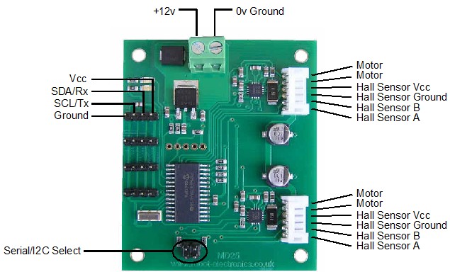
I hooked up the MD25 controller and it worked “out of the box” with my lib written for the MD23. No changes , except removing the jumpers to enable I2C mode , as the new version also features serial interfacing via the same pins..
A little thought is needed in order to decide the placing of the SRF-05 sensors , my dual-axis accelerometer is very light weighted , ( which is a good thing ![]() ) the IR Photoreflectors will be added in the base of the robot so it will not fall from stairs , and maybe able to follow lines using purely hardware operation ( i.e. the onboard PC being switched off )..
) the IR Photoreflectors will be added in the base of the robot so it will not fall from stairs , and maybe able to follow lines using purely hardware operation ( i.e. the onboard PC being switched off )..
Finally with the IR receivers plus IR leds I plan to make the robot be able to respond to remote control commands , and being also able to switch on/off electronic appliances ( TV , Aircondition , w/e )
All i need now is some spare time , cables , and maybe a new soldering iron ;P
Just ordered new parts from Active-Robots
August 31st, 2010I just order new parts for guarddog after raising money during summer ![]()
The new parts I will be including to the design are
1x Mesmsic 2125 Dual-axis Accelorometer
4x Piezo Film Vibra Tab Mass
1x 12V 2.8A Dual H-Bridge MD25
2x SRF05 + Mounting Hardware Kit
2x Fairchild IR Photoreflector
2x Infrared Optical Sensor
Cant wait to have them!
Also during the last week I started a deviant-art gallery ( http://ammarkov1.deviantart.com/ ) , automatic slideshow ( http://justsitback.deviantart.com/?title=AmmarkoV1%27s%20gallery&rssQuery=gallery:AmmarkoV1/26376777 )..
And I also started writing a slideshow application ( http://github.com/AmmarkoV/FlashySlideshows ) ![]()
On other news , I will be joined Greek military in november ( military service is compulsory for 9 months in Greece ) so I have to make the following months count !
MD23 shorted out :S ?
July 30th, 2010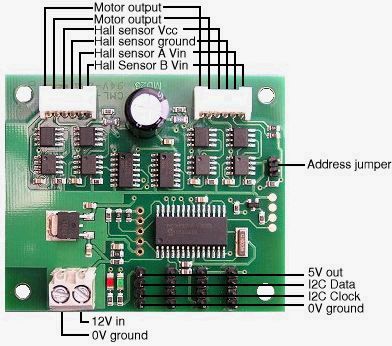
After powering up guarddog after my summer vacations it started moving in an erratic way front and back before the motherboard booted , I immediately pulled out the power cable but now the MD23 board wont even power the red led ( that signals that the board has voltage on its ends ) the board seems to be fried ( http://www.robot-electronics.co.uk/htm/md23tech.htm ) , but I have no idea why..
The USB 2 I2C module seems intact and so does everything else
I will have to order a new one but since the MD23 controller is discontinued I will have to go with the MD25 one ( http://www.robot-electronics.co.uk/htm/md25tech.htm )
It is a pretty big set back since I was about to start meshing together 2D snapshots to a 3D world representation using the data from the motor encoders but now I have to wait for the order to ship from England and then rewire everything etc..
Anyways , 3 interesting videos !